
IMPROVER
While designing our first rover Improver we set out to make it low cost, easy to assemble/disassemble, resilient against impacts and the environment. After almost 2 years of work, our design has been finalized and production has begun. All sub-systems of the Improver are listed below.

DRIVELINE
Aluminum box and sigma profiles were used in the structure of our rover for ease of assembly. The dimensions of the frame were determined according to the hardware that it will house.
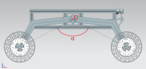
After research and analysis according to the rocker system has been designed with the optimum dimensions. For our Rover to maneuver easily through rugged terrain with ease “Passive Rocker Suspension System” has been used which enables it to keep maximum contact with the ground even when crawling over obstacles.
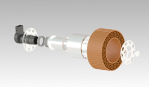
Wheels which are one of the key components of the movement system house the motors inside concealing it from any damage that may come from impacts, rocks, and dirt. The dimensions have been defined according to the terrain we’re expected to traverse.
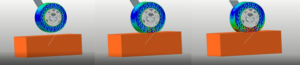
As the rover does not have an active suspension system that can absorb vibrations and impacts, the wheel has been decided to be manufactured with the FDM method and TPU filament as the material after some dynamic analysis. After the analyses, the steepest slopes and obstacles that the rover can climb over are determined.
ROBOTIC ARM
 The robotic arms structure has been determined throughout the kinematic analysis, and it will have 6 degrees of freedom. The design was finalized considering forces acting on the system, stresses, and materials used in the manufacturing.

The end effector of the robotic arm was designed for optimum performance and flexibility when doing different tasks. Taking soil samples, operating the control panel, and collecting green samples from the surface are some of the tasks it will be required to perform.
SOIL SAMPLING SYSTEM
 During the Science Task, the rover will be expected to gather 3 samples from the surface and one deep sample from 30cm below the surface. After collection, it will be required to run various analyses on the samples.
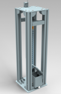
While the Robotic Arm system will be used to gather surface samples. A separate Soil Sampling Drill system will be put to use to collect soil from 30cm under the surface. The Soil Sampling Drill has been designed for ruggedness and ease of mounting. Sigma profiles have been used for the structure and thanks to the geometry of the Auger it is able to transfer the sample to the analysis equipment.
Later the analysis equipment runs a range of measurements on the sample consisting of moisture, temperature, volume, and weight. Additionally, a low-budget spectrometer will check for elements inside the sample which can be used to determine if there is life.
CONTROL OF ROVER
 With the help of encoders and various sensors, the motors and actuators are controlled independently with the help of the ROS interface. Locomotion, drill sampling, and robotic arm are all controlled via specialized motor drivers that are our own design.
IMAGE PROCESSING
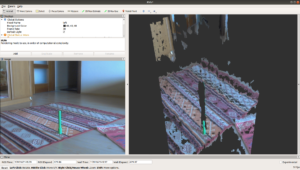
 To determine the position of the rover during the navigation task ARTag recognition is used in conjunction with feedback from the drive encoders. The Relative position and distance of the ARTag Beaconsare calculated via a specialized ROS library.
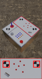
For determining the position of the samples during the collection task stereo-cameras are used. After recognizing the objects through their color the object’s position and orientation are determined.
During the maintenance task again stereo-cameras are used to recognize buttons, and switches and calculate the relative distance to the end effector.
Lastly on the science task image feed is used to measure the hue of the soil and collect the sample accordingly
MOTION PLANNING
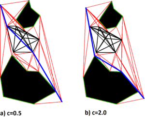
After the position of the rover is determined, motion planning algorithms are used to calculate the optimum path that the rover will follow. Additionally, if the rover encounters any objects on this path, the stereo cameras, and ultrasonic sensors are used to guide the rover to maneuver around the object with the help of shape, distance, and orientation data that is gathered.
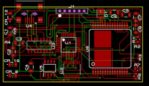
POWER DISTRIBUTION
As the Rover cannot have any tethers to the base station it must carry all of the energy required to complete the mission on-board. Power is stored on Li-Po batteries and distributed throughout the rover with the help of a power distribution and regulation board.
COMMUNICATION
With the help of the CAN-BUS line on the rover, data is read & written on a single pair of wires reducing the need for additional wiring and using a central processing unit by reducing the need for additional operations.
During ERC the communication will be held over Wi-Fi. The transceivers will enable the rover and the control computer to relay information to each other in real-time.